
Desk with HAIRPIN LEGS In Shapr3D - CAD Design For Woodworkers
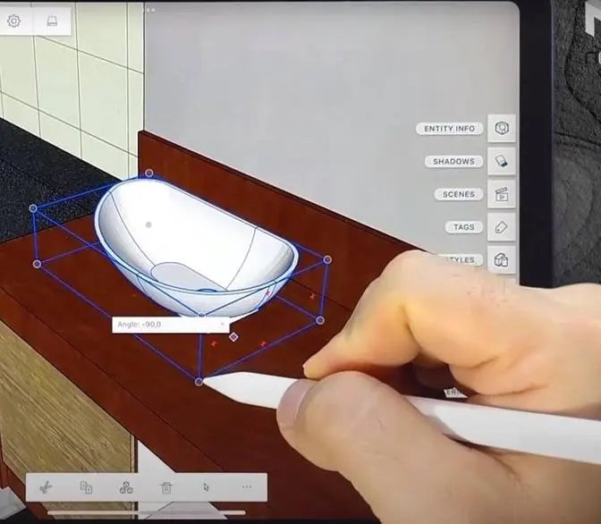
Thanks to Shapr3D for sponsoring this video.
Today, we are gonna model this desk
with an attached filing cabinet on the side
and some hairpin legs.
And we're gonna show you how to set this up
so everything will scale together
when we make adjustments to any single parameter,
which is extremely useful for quickly showing clients
the changes that they wanna see
and how those changes can affect the entire piece.
So if you haven't yet,
be sure to use the link in the description
to download your free copy
of the Shapr3D Parametric Modeling Beta
so that you can follow along.
And then later, if you wanna upgrade to the pro version,
you can save 10% by using my code
BEVLISHCREATIONS10 at checkout
and unlock the full potential
of this really amazing program.
Anyway, guys, enough talking.
Let's get started.
As usual, we'll be modeling in millimeters
and I'm gonna lock my grid size to one millimeter.
Now, we're gonna start by defining
the total height of our desk.
So to do that, let's go and add a construction plane
and we're gonna keep the default type as offset.
And now we're gonna pick this bottom plane,
click next, and then we're gonna drag this up
750 millimeters and click done.
All right, now let's go to our plane
and actually a quick way to get to that plane
is just double click on this navigation cube right here.
There we go.
All right, let's start sketching on this plane
and we're gonna switch over to the rectangle tool
to draw our desktop.
So starting from the origin
and we're just gonna drag this out like that
and we're gonna make the width 1800 millimeters
and set the depth to 700.
All right, now let's spin out of this view
and we're gonna pick this closed surface
and extrude this downward 25 millimeters.
And there's our desktop.
All right, I just wanna mention
that since my last video was uploaded,
Shapr3D added a bunch of new features to this beta
and I just wanna show you guys real quick what those are.
So if we go to the items manager,
you can see that when I made this extrusion,
the sketch is automatically hidden.
If we bring that back,
you'll see that our dimensions are always showing now
and we can actually change these dimensions
without going into the sketch, which is really nice.
And they also made some changes to the font.
So now these measurements are a lot easier to see.
But another major feature that they added
is now we can go to the history sidebar
and rename these steps,
which is really important for parametric modeling
because as we start building out our model
and this list start getting longer and longer,
it can be really difficult
to figure out what each step is for.
So it's really nice to be able to come in here
and rename these.
So let's change this plane to overall height
and let's add a couple of asterisks in front of it
so it can quickly catch our attention.
Let's change this sketch to desktop width and depth
and the extrusion to desktop thickness.
And you probably noticed
that when I changed the name of the sketch,
the same name will be reflected
in the items manager as well.
And this only happens for the sketches right now,
which I don't mind because I'd rather rename this body
to desktop instead of the desktop thickness over here.
But I do wish that the planes
could rename automatically as well
because I can't think of an example
where I would want these to be named differently.
But anyways, I digress, guys.
Let's flip to the bottom
and we're gonna pick these four edges
and we're gonna add a bevel on the bottom.
But instead of using an automatic chamfer,
I'm gonna change the type to two distance chamfer.
And I'm gonna go up 22 millimeters this way
and then 30 millimeters this way
so that we end up with an angle of 36 degrees,
which I think it looks better
than a regular 45 degree bevel,
but that's just personal preference.
All right, so now we're ready to move on
to making the cabinet.
And what I want is for the cabinet
to always be flush against these three edges right here
so that for whatever reason in future,
if I want to change the size of these bevels,
our cabinet will always scale with it.
So to do that, let's add a new construction plane.
And this time we're gonna change the type
to parallel to face.
And let's zoom in here.
And this is the face that we're gonna pick.
And then click next and flip to the bottom
to pick this edge right here.
And we're gonna drag this point
until it snaps to this corner and click done.
So what we just did here is
if we change the size of this bevel,
you can see that our plane is going to move along with it.
All right, let's undo and start sketching on that plane.
And the first thing we wanna do is zoom in here
and start sketching a line at the origin.
And we're just gonna drag this to the right.
And the length of this guy doesn't matter,
but what's important is when we select this line,
we should see this horizontal vertical constraint
right here, meaning that this line is perfectly horizontal.
And once you see that,
let's turn that into a construction line
and then lock it in place.
All right, now to make sure the side of our cabinet
is flush to this corner right here,
let's draw another line starting from this corner
all the way down until it snaps to our ground line.
And when we hover over this point,
we should see these two constraints.
One is the coincident constraint
and the other is the perpendicular constraint,
which means our line is perfectly vertical.
Now let's pick this line
and turn it into a construction line.
And we don't wanna lock this line down
because when we change this bevel here,
we want this line to be able to move
from side to side like that.
All right, now let's go back to our sketch,
go to a front view,
and let's switch over to the rectangle tool.
And we're gonna start sketching a rectangle on this line
and just drag it down.
And let's double click on this rectangle
and use the horizontal vertical constraint
to lock down its orientation.
And now we're ready to give it some dimensions.
All right, we want the bottom of the case
to be 100 millimeters off the ground.
And then we want the top of the case to be,
let's do 70 millimeters from the desktop.
And let's make the total width 450 millimeters.
All right, now to define the thickness of our panels,
let's use the offset edge tool
and make sure that the type is set to loop.
And we're gonna pick one of these lines
and just drag it down 20 millimeters.
So like I've complained in my past videos,
even though we just defined the amount of offset here,
we still have to come in here and manually set the gaps,
which, you know, it's not a big problem
for direct modeling.
We don't have to do this step,
but it is really important to do this
for parametric modeling.
So I hope Shaper 3D get this fixed
because I'm gonna keep mentioning this
until this is fixed.
But anyway, guys, let's switch back to the line tool
and we're gonna draw some lines from corner to corner
to make our miter joints.
And now we are ready to extrude these.
So let's rotate out of that view.
And remember to extrude these,
we can't pick all four at the same time
and extrude them together
because it's just gonna create a single body.
So what we wanna do is pick two faces
that are not touching, extrude those first,
and then pick the other two faces and then extrude those,
which will give us the four separate bodies that we want.
All right, let's spin to the back.
So for the depth of this cabinet, like I said earlier,
I want it to be flush to this edge right here.
So what I normally would do
is go to the extrusion properties over here
and change this extent to point.
But unfortunately in this beta version
that I'm running right now,
which is version 6.1.6.0,
there's a bug where it's not giving me the option
to choose the feature that I want to extend to.
So what I should be able to do
is pick this bevel face right here
and this panel will extend to the closest point,
which would be this edge.
But unfortunately when I pick this, nothing happens, right?
So the workaround for this right now
is change the extent to object.
And now we get the option to pick our object.
So click on select and then pick our bevel face,
click done.
And that cuts our panels like this,
which is obviously not what we want.
But when we go and change this extent back to point,
it fixes that.
So now if we go to a left view,
you can see that our panel is flush against this back edge.
So chances are by the time you're watching this video,
this problem is already fixed
because there seem to be this pattern
where right after I release a new video,
they'll come out with an update
that fixes all these problems
and give us new features.
But just in case that the bugs is still there,
this is the workaround for it.
Okay, now let's expand the extrusion properties
for our other two panels.
And we're gonna change this extend to object.
And for the object, we can pick the back face
of either of these side panels
and click done to finish that guy up.
So basically our two side panels
are tied to this bottom edge right here
and the top and bottom panels
will follow whatever the side panels will do.
So if we go to our chamfer
and start making adjustments to it,
our case will update with it.
All right, let's undo that.
And now let's hide the planes and sketches
that we don't need and flip to the front
because I want to add a bevel along the inside edges here.
But this time we're just gonna use an auto chamfer
so that they're 45 degrees,
but we're still going to keep three millimeters
of flat around it
because I just really like the way that looks.
Okay, that's it for our case.
And now we need to add some supports in between here,
which is pretty straightforward.
All we have to do is select this top
and then we're gonna use the isolate tool
to hide everything else.
And we are gonna start sketching on the surface.
All right, let's sketch a circle right here
and we'll make that diameter 30.
And let's zoom in here
and we'll set the distance between the center to edge
at, I don't know, 50 millimeters.
And let's do the same thing for this edge as well.
Okay, now let's spin out of that,
pick that surface,
and we'll extrude that up to some random length.
And make sure to click on this little button right here
and select new body
so that this guy doesn't automatically get combined
with the top panel.
All right, now let's turn off isolate
and bring everything back.
And we're gonna go to the extrusion properties for this guy.
Let's minimize the other stuff
and we'll extend to object.
And then for the object,
we'll pick the bottom face of our desktop
and click done.
All right, so we've got one support.
Now to create the other three,
we're just gonna use the mirror function.
But first we need to create some mirroring planes.
So go under add construction plane,
but this time for the type we'll use mid plane.
And for this first one,
we're gonna use this front face right here
and then this back face.
And click done.
And then create another mid plane.
And this time we'll use the two side faces.
And click done.
All right, now to mirror this guy over,
come under transform, select mirror,
and then we'll double click to select that guy
and then pick either of these planes that we just created.
And click done.
And then we'll repeat that again,
but this time we'll select both of these guys
and then pick the other plane.
And click done to finish those guys up.
All right, now let's hide all these sketches
and planes again.
And if we make any changes to our chamfer,
let's see what happens.
All right, everything is moving together.
And we change the overall height.
All right, that looks pretty good.
And let's see what happens if we change the dimensions
for our case right here.
So if I change that to 100, it'll extend with it.
All right, so we're making pretty good progress
and you can see that our list of stuff
is getting pretty long.
So let's come in here and start renaming some of these.
And you know, even if we don't rename every single feature,
we should at least do it for the ones
that we'll likely reuse later on.
And add some asterisks in front of those
so we can quickly find it in the tree.
And while we're at it, it's also good practice
to group the features in the Items Manager into folders.
And the reason why I didn't put these two planes in there
is because we're likely gonna use them later.
So for this one, we are going to rename it
the same as over here.
So it'll be Cabinet X Midplane.
And this one will be Cabinet Y Midplane.
So pause the video here if you need to
and get your workspace organized.
And once you're ready,
we're gonna start making our drawer boxes.
So for these, let's zoom in here
and also hide our two midplanes.
And we're gonna start by making a new construction plane.
And this time we're gonna offset
from this face right here.
Click Next and push this plane back 37 millimeters.
And click Done.
All right, now let's start sketching on this plane.
And we're gonna start by drawing a rectangle
from corner to corner like this.
And let's double-click on this rectangle
and then use the horizontal-vertical constraint
to lock down its orientation.
And this rectangle is what we're gonna use
to help set the gaps for our drawer boxes.
So let's double-click on that
and we're gonna turn it into a construction geometry.
All right, so for this cabinet,
we're gonna have three drawers.
So let's draw three rectangles inside here.
And this bottom one's gonna be larger
because we're gonna use it to store some file folders.
Based on my past experience building something like this,
we're gonna set this height to 250 millimeters.
And if we're using those under-mount drawer slides,
we're gonna set this bottom gap to 14 millimeters.
And then the side clearances to 13 millimeters
for both sides.
All right, and we're gonna do the same
for the top two drawers.
So set the side clearances to 13 millimeters
for those as well.
And then let's set the gaps to the top of the drawer boxes
to 30 millimeters for all of these.
And lastly, we want these two top drawers
to be the same size.
So to do that, let's pick the vertical lines
on both of these
and then use the equal constraint right here.
All right, so let's spin out of this
and let's change the overall height of our desk.
You can see that the bottom rectangle stays the same size
while the top two are scaled together
but remain the same size.
Let's undo that.
And we're gonna extrude these three guys back 12 millimeters.
All right, now, before we move on
to creating the side panels,
we need to cut some dados in here for our drawer bottoms.
So let's pick all three of these
and then use the isolate tool so we hide everything else.
And then we're gonna come to the side face
and start sketching on it.
And let's choose the rectangle tool
and we're gonna draw rectangles like this
on all three of these drawer boxes.
And then let's set some dimensions for these.
So all of these are gonna be six millimeters wide
by six millimeters deep
and the distance to the bottom will be 13 millimeters.
Let's repeat that for all of these.
Okay, now let's spin out of this
and we're gonna pick all three of these surfaces
that we just created
and then we're gonna push them out.
And just like what we've done
with all the extrusions up to this point,
we'll come over here to the extrusion properties
and then change this to extend to object.
And then for the object,
we're gonna pick the face on the opposite side
and click done.
This way, no matter how long these panels get,
our cutout will always extend to this face.
So we're ready to move on
to making the side panels for our drawer boxes.
And I'm just gonna keep the joinery relatively simple
by using rabbits
because I don't want this to turn into a one-hour video.
But if you are interested to see more complex joinery
like dovetails or box joints,
I have another video specifically on that.
So be sure to check that out.
All right, let's get back to this
and we're gonna start creating another sketch
on the side face here.
And this time we're gonna draw another rectangle
or let's go to the top one first.
And we're gonna go from midpoint down to midpoint
and just drag it out to the left like this.
And we'll repeat the same thing for all three of these.
And then let's zoom out,
just double click on all three
and we're gonna use the horizontal vertical constraint
to lock down its orientation.
Now to define the length of these,
let's turn off isolate and bring everything back.
And then we're gonna draw a line
from this top corner down to this bottom corner.
And let's pick that line
and turn it into a construction line.
All right, now let's select our sketch over here
in the items manager,
turn on isolate again.
And all we had to do is set this distance right here.
We're gonna do 25 millimeters.
And then let's pick these horizontal lines right here.
And then we're gonna use the equal constraint.
So now no matter how deep our cabinet is,
our drawer boxes will always be 25 millimeters
from the back edge.
All right, so now let's spin out of this
and we're gonna extrude all three
of these 12 millimeters toward the inside.
And now let's go to the front
and we're gonna start sketching our dados
for the drawer bottoms.
And just like earlier,
we're gonna set these dimensions to six by six
and then 13 millimeters to the bottom.
And then let's spin out of that.
Oops.
And then pick these squares that we just created
and push them out to get them cut.
And just like earlier,
we'll go to the extrusion properties
and change this to extend to object.
And for the object,
we're gonna pick the back face of our drawer box
and click done.
All right, now let's bring everything back
and then hide all the sketches and planes
that we no longer need.
But then we're gonna bring back this cabinet X plane
because we're gonna use this as a mirroring plane
to mirror these three guys over to the other side.
So select those three and then come down to mirror
and then pick this plane right here and click done.
And then now to mirror these front panels to the back,
we can't use this cabinet Y mid plane
because our drawer boxes doesn't sit
in the middle of our cabinet.
So instead, let's hide these planes.
We actually need to create a new plane.
So let's select this guy and isolate just that
and then add construction plane,
change the type to mid plane.
And we're gonna use the back face and front face
and click done.
All right, now let's bring everything else back,
choose these three panels here,
go under more, mirror,
and then pick that new plane we just created
and click done.
All right, there we go.
Now to make the drawer bottoms,
what we have to do is isolate our side panels.
So pick out six of those,
isolate, and all we have to do is zoom in here,
pick these faces in the dados.
Before we extrude those,
we have to change this from offset face to extrude
and then pull those out.
And make sure to click on this little icon
and select new body.
And then once again, we'll come to the extrusion properties
and we'll extend to object.
And for the object,
we're gonna pick this face in the opposite dado
and click done.
All right, there we go.
Now let's bring everything back
and we're actually gonna filter this
to only show the bodies.
And we're gonna select all of these bodies
for our drawer boxes and isolate those
because we need to cut our rabbits.
So to do that, let's go under tools
and use the subtract function.
And we're just gonna pick everything right here,
except for the drawer bottoms.
Let's flip to the front and pick these.
So what we want is for all the front and back panels
to be plus signs
and then all the side panels to be minus signs.
And the last one right here and click done.
There we go.
We've got our rabbits cut out.
All right, now all that's left is to make some drawer fronts.
Once again, we'll bring everything back
and let's hide all the planes and sketches
that we don't need.
And for the drawer fronts,
we're just gonna start sketching
on this front face right here.
The process is pretty much the same
as what we did for the drawer boxes.
So let's start by drawing a rectangle
from corner to corner.
And once again, we're gonna be using this
to set our gaps for our drawer fronts.
Let's double click on that,
turn on horizontal vertical constraint
and then double click on it again
to make it into a construction geometry.
All right, and we're now just gonna isolate the sketch
so we can see what's going on here.
Like what we did earlier,
we'll draw three rectangles in here
and this time we'll set all the gaps to three millimeters.
But then we'll set the height
of the bottom drawer front to 285.
And to ensure that the top two drawer fronts
are the same height,
we'll pick both of those lines right there
and then use the equal constraint to finish that up.
And now let's spin out of that view
and we're gonna select all three of these
and pull those out 20 millimeters.
All right, now let's bring everything back
and let's double check to make sure
that everything is updating together, which they are.
And let's change the height and see what happens.
650.
All right, everything looks really good
and everything's updating the way they're supposed to.
Now, before we move on to the legs,
let's start renaming some of these features
and get our workspace organized.
All right, we are ready to move on to the most exciting,
or at least I think so,
the most exciting part of this whole video
and that's how to model some hairpin legs.
And I've never done this before, it was brand new to me.
So it took me a little time
to figure out how to do this correctly
and it can get a little bit complicated.
So if you wanna learn how to model this,
I highly recommend not skipping around.
And even if you're doing direct modeling,
I would say 95% of the steps are exactly the same.
But anyway, I already did some quick Googling
to get some basic dimensions.
So let's flip to the bottom
and we're gonna start sketching on this face here.
And we're gonna use the line tool
to sketch a random upside down L shape.
So something like that.
And let's double click on this
and use the horizontal vertical constraint
to make sure all our lines
are perfectly horizontal and vertical.
All right, let's set the length of this to 130 millimeters
and then the length of this line
will also be 130 millimeters.
Oops, let's drag this guy back down
and we'll set that to 50.
And this will also be 50.
And let's switch over to the circle tool
and we're gonna sketch three circles in here
for our mounting holes.
Let's pick all three circles
and use the equal constraint
so that we only have to set the diameter for one of these
and the other two will update automatically.
And we're gonna set this distance here to 10 millimeters
from center to edge and same thing for this one.
And then we're gonna repeat the same thing
for the other two circles as well.
And the last thing we need is to set this gap
to the edge of our desktop.
I don't know why that dimension went all the way over there.
Let's set that to 60 millimeters
and do the same thing to this.
Let's spin out of this and we're gonna pick the surface
and extrude that up three millimeters.
And don't forget to click on this little button
and make sure that it's a new body.
All right, so for this base plate,
if we change our desktop bevel,
it should move along with that corner, just like that.
Now we can finally move on to the legs.
So let's hide this sketch.
Actually, let's rename this sketch to base plate definition.
All right, now let's hide it.
And we're gonna start another sketch
on the top of this base plate.
And the first thing we wanna do is draw a line
from this midpoint all the way
to this opposite edge right here.
And then draw another line from this midpoint
to the opposite edge.
And these are the two lines we're gonna use
to help us define the position of our rods.
So let's pick both of these lines
and we're gonna turn them into construction lines.
All right, now let's use the circle tool
and we're gonna draw three circles.
One's gonna be on this edge right here,
another one at this intersection
and a third one on this line.
And just like earlier, we'll pick all three circles
and make them equal to one another.
And we'll set the dimension for just one of these.
The distance from center point to edge
is going to be 25 millimeters
and the same for this one as well.
All right, so like I said earlier,
these three circles are going to be the position
of the rods on this plate.
And now we need a way to define the angle
of our leg like this.
So in order to do that,
we actually need to stay in this sketch
and first sketch a line from this center point
to this center point.
And we'll turn that into a construction line.
All right, now we can exit this sketch
and we're gonna add a new construction plane.
And the type for this one will be perpendicular to edge.
And for the edge, we're gonna select this line
that we just created and click next.
And then for the center point,
we're going to click on the circle
so that point is placed at the center of that circle
and click done.
All right, so let's start sketching on this plane.
And the first thing we need
is to actually define the ground line.
So let's move up here and we're gonna zoom in
and sketch a line on this axis.
Like I said earlier, for these ground lines,
the length doesn't really matter,
but we wanna make sure
that we see this horizontal vertical constraint.
So we know that it's perfectly horizontal.
All right, let's pick this line,
turn it into a construction line and lock in place.
All right, now let's go back down to our table
and actually we need to move out of that view
so we can draw a line starting
from the center point of this circle
and pull it up like that.
All right, now let's click here
to go back normal to our sketch
and pick this line
and use the horizontal vertical constraint
to make that line vertical.
All right, now let's grab this point
and we'll just drag this up.
And from here, we're gonna draw a horizontal line
from this end point and make sure that's horizontal.
And then we'll draw a third line
connecting back to this end point down here.
All right, double click on this
so that all three lines are selected
and we're gonna turn all three of them
into construction lines.
All right, so for the distance here to here,
it should be half of the thickness of our rod.
So that would be 6.5 millimeters.
And then we're gonna set the length of this guy to 100.
All right, so this is a sketch
that we're gonna use to define the angle of our leg.
So let's exit out of that
and we're gonna rename this sketch
to Leg Angle and Length Definition.
Before I forget, I'm gonna rename this one too
to Leg Position Definition.
All right, so we're not quite done yet.
We actually need to create another construction plane.
And this time we're gonna set the type to three points.
And for our three points,
the first one is going to be the center point
of this circle.
Second point is the center point on this circle.
And then our third point is going to be
this vertex right here.
And click Done.
And this is the plane that we're gonna use
to define the curvature of our leg.
So click on that and start sketching on it.
The first thing we wanna do is draw a line
from this bottom point here straight down
and make sure that it's vertical.
And we're gonna set the length of that to 25.
And let's turn that line into a construction line.
Okay, now switch over to the circle tool
and we're gonna draw a circle
starting from this end point down here.
And the diameter of that will be 50 millimeters.
All right, switch back to the line tool now
and we're gonna draw a line from this circle
down to the center point on this circle.
And we'll do the same thing over here.
So starting from the center point of this circle
and go up to this circle here.
Let's zoom in here.
We'll pick this circle and this line
and make them tangent to one another.
And do the same thing over here.
Tangent.
Now let's use the trim tool
to remove the bottom half of this circle.
So now just grab any of these points
and drag it around and make sure that nothing is moving.
Because like I said in my previous video,
sometimes when we use the trim tool,
it'll also delete our constraints
which we definitely don't want.
So now if we go back to our leg angle and length sketch,
if we change this, everything else should change with it.
That looks pretty good.
If we change this, that's scaling together as well.
All right, so now we have everything we need.
We can start creating our actual leg.
So to do that, we're gonna go to tools
and use the sweep function.
And for our face,
we're going to pick this circle right here, click next.
And then for our profile,
we're going to pick this thing that we just created
and click done.
All right, if we zoom in here,
we actually have a small problem.
Actually, let's hide some of this stuff that we don't need
so you can see it better.
So you can see that this end of our rod
is not matching our base plate.
So to fix that, let's go under tools
and we're gonna use the replace face tool.
All we have to do is pick this face here
and then the face on our base plate and click done.
There we go.
All right, now we just need to create
this third support rod.
So to do that,
let's bring back our leg position definition sketch
and then the angle and length definition.
And we're gonna use the sweep tool again
and we're gonna pick this circle right here, click next.
And then it will be this line here and click done.
All right, so because of the two different angles
we have here,
there's actually a small little problem
right at the end right here.
You can see there's a sliver of material
right here that's showing up.
We can get that fixed pretty easily.
Just grab the edge
and we'll add a small fillet right there.
So let's do three millimeters.
Now let's grab both of these bodies
and then use the union function
to combine these into one body.
So now we have this additional edge
that we can use to add another fillet
to clean up this joint.
So with the actual hairpin legs,
they actually have wells down here anyway
to cover up this joint.
So I think what we have here
is actually pretty good representation of that.
Anyway, let's zoom out here
and we're gonna pick our leg assembly
and our base plate down here
and use the union function
to make them into one body.
And let's also hide all the sketches
and planes that we no longer need.
And while we're here,
let's pick all the sharp edges and corners here
and we're just gonna give it a small round over.
All right, now let's bring back
our cabinet Y mid plane
and we're gonna use this guy
to mirror over our leg.
So let's pick that guy
and this plane and click done.
So once again,
if we go up here
and change our desktop bevel,
both legs should adjust together.
So that looks good.
And oops, let's flip to the front.
And if we change the overall height,
let's do 650.
Our leg will shorten
instead of moving down with it,
which is perfect.
And if we ever need to make any changes
to the angle of this,
we just need to go to this leg angle
and length definition
and we change that to 200.
That looks really good.
I actually like this.
I'm gonna keep it this way.
Anyway, let's move on
to making the legs for the cabinet.
And honestly, I wish there was a way
to take everything that we've done over here
and just move it over to the cabinet side
and make some adjustments
and make it fit.
But unfortunately,
I could not figure out a good way to do this
and still make it fully updatable.
So we're gonna have to redo those steps
for our cabinet legs.
But hey, on the bright side,
we can quickly review everything we've done.
So let's flip to the bottom side of our cabinet
and we're gonna start sketching on it.
And just like earlier,
we'll draw our upside down L shape.
Double click to make sure all the lines
are horizontal and vertical.
We'll set this dimension to 130.
This one will also be 130.
50 millimeters for the shorter sides.
And since these are shorter legs,
we're gonna keep this distance here.
Let's do 15 millimeters.
And let's zoom back in here
and we'll draw our mounting holes.
Make all three of these equal to one another.
And we'll just set the diameter for one of these.
And then set some of these distances
from center to edge to 10 millimeters.
And once again, do it for the other circles as well.
All right, exit the sketch.
Let's spin out of that view.
Extrude that up three millimeters.
Make that into a new body.
And let's hide that sketch.
And actually, let's come down here
and we'll rename that sketch
to cabinet base plate definition.
All right, now let's draw on the top surface
of this base plate.
And we're gonna start by making two center lines.
Turn those into construction lines.
And one circle on this line,
one circle on the intersection,
and another circle here.
Make all three of these equal to one another.
Set the diameter to 13.
And then the center to edge distance is 25
for both of these.
Before we exit that sketch,
let's go back to the line tool
and we'll draw a line connecting the centers
of these two circles.
Turn that into a construction line.
All right, let's spin out of that
and exit the sketch.
We'll add another construction plane.
The type will be perpendicular to edge.
We'll pick this line, click next,
and then this circle right here.
Click done.
All right, and we're gonna start sketching on this plane.
First thing we're gonna do is come up here
and define our ground line.
Turn it into a construction line and lock in place.
And then we're gonna draw a vertical line up
and then horizontal this way.
And then back down to our starting point.
All right, double click to select the whole thing
and turn it into a construction line.
We'll set this gap to 6.5.
And since this is a pretty short leg,
we don't want this to be very long.
So let's just do five millimeters for now
and see how that looks.
All right, now let's exit the sketch
and we're ready to make our next plane.
And this time the type will be three points.
First point will be the center point of that circle.
And then second point is the center point on that circle.
And our third point is this vertex right there.
And click done.
And yeah, you can see how severe that angle is.
So let's actually go back to this
and we're gonna unlock that dimension.
I'm gonna drag this point this way instead.
And then let's set that to 15.
So I think that will look a little bit better.
Actually, let's do 30.
Yeah, that looks a lot better.
All right, let's start sketching on this plane now.
And we're gonna sketch a line from that point
down 25 millimeters.
Pick our line, turn it into a construction line.
And then we'll sketch a circle on that end point
with a diameter of 50 millimeters.
Switch to the line tool and we'll draw a line
from this circle down to the center point
of this circle down here.
And we'll do the same thing over here.
All right, pick this line and the circle,
make them tangent.
Pick this line and the circle and do the same thing.
All right, now use the trim tool
to trim away this bottom half.
And just drag this point around
and make sure that everything is still constrained.
Okay, everything looks good.
Let's exit the sketch and we'll switch to the sweep tool.
Where is it?
Oh, here it is.
Let's pick that circle, click next,
and then click our profile and click done.
All right, now let's rename this sketch
to cabinet leg definition.
And this other one will be cabinet leg angle
and length definition.
Let's hide this guy real quick.
And we're gonna use the replace face tool
to match up this face to our base plate and click done.
Bring back our sketch right here to make our support piece.
So go to tools, sweep again,
and use this circle, click next,
and this guy right here, click done.
Okay, let's hide all the sketches
and planes that we don't need.
Similar to before, we're just gonna pick this edge
and add a small one millimeter radius.
And then let's pick both of these guys
and use the union function to combine them together
so that we can pick this edge
and add a small fillet on there to clean up this joint.
All right, let's zoom out a bit.
And we already have the cabinet Y mid plane here.
We're also gonna bring back the cabinet X mid plane.
Oh, before we mirror things over,
I forgot we need to pick this guy and our base plate
and combine them into one body as well.
And we should also come in here,
select our sharp edges and corners,
and add a small fillet.
All right, now we can start mirroring things over.
Let's go to our mirror tool,
and we're gonna select this leg and this plane,
click done, and then we're gonna repeat that.
Select the mirror tool, pick both of the legs,
and then this time we'll mirror it
about this plane right here, and click done.
While modeling this,
I just remembered that on shorter hairpin legs like these,
they usually don't have this third support piece on there,
which is why this looks kind of weird, right?
The good news is we use parametric modeling to create this,
so we don't need to redo anything.
And a great way to use the timeline over here
is if we come in here and pick the support rod,
you'll see that our timeline will update
to show only the steps that were used
to create this guy here.
So we know that it was created using the sweep.
So what we can do is click on this little circle
with the three dots, and click on suppress.
So what that did was that it removed the step
and all the steps associated with it
without actually deleting anything.
So let's say for some reason,
our client looks at this model and thinks,
those legs look a little weak, can we strengthen it?
We can actually come over here and unsuppress it,
and bring that back and show them
what that would look like.
Anyway, we're finished with modeling,
and now let's just double check
to make sure everything's updating correctly.
If I change the overall height,
the length of our legs and cabinets are updating correctly.
Now if I change the bevel,
everything's scaling together as well.
All right, let's undo that.
And let's go to our cabinet dimension.
And if we want to change that bottom edge to be lower,
our shorter legs are updating correctly as well.
All right, everything looks good.
Let's hide that support rod on these shorter legs
because I really don't like the way they look.
Okay, so we are done with designing this guy.
I think this was probably the first time
that my computer actually had to do some thinking
while I was making these updates.
But that just goes to show how heavy this model was.
And yeah, if you guys enjoyed designing with me,
be sure to leave me one of these.
And if you haven't yet,
be sure to hit that subscribe button,
and I will see you guys in the next video.