
Furniture JOINERY Design on the iPad Pro Shapr3D || Woodworking
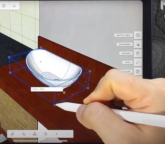
Thanks to Shaper 3D for sponsoring this video and supporting my channel.
Hello, here I am back with another Shaper 3D video, and I think this one is long overdue
because I've been asked for months by many of you to do a deeper dive into how to model
different types of woodworking joints, which happens to be something that Shaper 3D does
really well, so I'm really excited to finally have the time to make this video.
I'm going to guide you guys through step by step on how to model 9 different commonly
used joints in woodworking, and in this process, you're going to be able to learn techniques and
tools that can be applied to modeling other parts of the furniture as well.
So I hope you guys stick around, and yeah, let's dive right into it.
The first one we're going to look at is the miter joint.
So for this example, I'm going to start with the top panel and make that 1200 long by 400 wide.
And then let's extrude that to 20 millimeters thick, and this is going to be the top panel,
so I'm going to drag it, let's say, 600 millimeters for this example.
So roughly 24 inches, I think.
One thing I mentioned in my past videos is that sketches in Shaper 3D aren't connected to 3D parts.
That means I get to use this sketch to create a second panel.
And let's adjust its length to 450 millimeters.
Now I'm going to double tap and use these arrows to rotate it and then drag it to the side.
And then to create the 45 degree miters on the ends,
what I'm going to do is pick the inside edges on both ends of each of these panels,
and then just push them in toward the center.
There we go, just takes a couple taps.
Now to bring these two panels together,
I'm going to go under the transform menu and then select this align tool,
and then pick the edge on the side panel first,
and then this one on the top panel to snap these two together.
And finally, to finish this case,
I'm going to press and drag my pencil across to select both of these panels,
and then click this little plus sign here to rotate the copies 180 degrees.
And there we go, quick and easy.
Of course, this method creates 45 degree angles by default.
So let's say if I wanted to create a case that's not rectangular,
I can still start with this method.
But what I have to do afterwards is come in here and pick this 45 degree surface,
and then the edge that I want to rotate that surface around.
This will enable me to change that angle to whatever I wanted.
So that's how I model miter joints and chamfers in Shapr3D.
Now let's take a look at how to model dados.
I'm going to start on the panel from the previous example,
and double tap on the back surface to draw a rectangle using the rectangle tool.
Now I'm going to constrain it by picking the long edge and setting that to 20 millimeters,
and the short edge to 6 millimeters.
And then finally, I'm going to set the position by picking the edge of the rectangle
and the endpoint of the board.
And it's just some random value here.
And lastly, I'm going to tap on the rectangle surface
and push it into the body to remove the material.
I can push this all the way to the end or stop short to make a stop dado.
And if you've already used SketchUp or Fusion 360 before,
you probably are the expert on this.
But that's all you have to do to create dados.
Now let's move on to the rabbit,
which is created pretty much the same way.
I could draw either on the top surface here or on the back edge.
But since this panel is really long,
I end up having to zoom out to draw the rectangle
and then zoom back in to set those dimensions,
and then zoom out to cut that shape.
So it's actually just more efficient to draw on a side face instead.
But I can't simply draw on that mitered face
because the cut will go normal to the plane that I'm sketching on.
So how do I do this?
Well, we can actually create our own sketch plane,
and here's how I'm going to do that.
Come under the Add menu, pick Construction Plane,
and then under the Type drop-down box,
select Perpendicular to Edge at a Point.
And I'm going to pick the back edge
and then the point at the very end of this board,
and then click Done.
Now double tap on this plane,
and then we can start drawing our profile for the rabbit.
So usually I set the dimensions to 6mm by 6mm for the back panel.
And now I can push it all the way through.
Of course, you can still use the other method
if you don't want to mess with the construction plane,
but I just want to show you guys that this option is available
if that need ever arises.
Now let's take a look at the half lap joint,
and this is something that you rarely see in case construction.
So I'm going to make a workpiece that's,
I don't know, 50 by 500 millimeters,
and then extrude that to 40 millimeters.
I'm going to create a copy of this
and rotate it and set aside for now.
And let's go back to this first workpiece.
I'm going to double tap on this top surface
and start drawing a rectangle.
Now this dimension here should match the width of this mating piece,
which in this case is 50 millimeters.
And now let's push that down 20 millimeters
to remove half of that material.
And before going on to the next step,
I'm going to hide the sketch just to keep things clean.
Now if this mating part was exactly the same dimension
as this first part,
I would have just created the copy after this cutout was made.
But for the sake of this example,
let's just pretend that they're different.
And you know what?
I'm going to change the color of this mating part
just to drive that point home.
So I'm going to come over here to visualizations
and double tap on this part.
And let's change that to blue.
And now let's snap these two together using the align tool.
So I'm going to use the bottom edge of this blue part
and then the bottom edge of this orange part.
Yellow?
Orange?
Before I click done,
this is a really good example to show what the align tool actually does.
So it snaps the midpoints of the features that we used for alignment,
which in this case was the short edge on this blue part
and then the long edge on the yellow.
And once these are aligned,
we can then make further adjustments to it.
For this example,
I'm going to drag that blue part until it snaps to the end of the yellow.
So as you can see,
there's an extra step compared to the alignment we did in the previous example
because the features that we use for defining the alignment are different lengths.
And there's another way to move these parts together,
but I'm going to show you that in the next example.
Right now, let me just show you how to cut the material from the blue part.
So I'm going to go under the tools menu.
And in here, I'm going to select the subtract function.
And to use this tool,
I'm first going to pick the part that needs material removed
and then the part used for creating that cut.
So in other words,
the blue part first and then the yellow.
Now click done.
And we've got matching cutout in the blue part.
Simple, right?
Okay, as promised,
let me show you the other method of bringing these parts together.
And to do that,
let's take a look at the cross-slab joint,
which is basically the same thing,
but with the cutout placed somewhere along the length of the part
instead of at the ends.
So for this, let's just use these same two parts.
But this time,
I'm going to draw the rectangle somewhere in the middle of this part.
And once again,
this dimension here should equal to the width of the mating part,
which is 50.
And in a real project,
I'll probably need to set this position as well.
So let's go ahead and do that before I remove half of this material.
Okay, so now it's time to move these two parts together.
But let's say for this project,
I want the blue part to extend about 50 millimeters past this yellow part.
If I went with the align tool,
I would pick the bottom edge of the blue part
and then the bottom edge of this yellow part,
just like we did before,
and then drag it over until it snaps to the cutout.
But now I'm gonna need to double tap on the blue part again
and drag it this way by 50 millimeters.
Okay, it's not bad,
but it can get complicated if there are angles involved.
So the better tool to use is the translate tool.
But before we do that,
we have to define the position of the cutout on the blue part first.
So I'm gonna double tap on one of the faces
and it can be either a top or side face.
It doesn't really matter.
I'm gonna draw a line on that face
and let's set this distance to 50 millimeters.
Now let's exit the sketch
and go under the transform menu
and pick the translate tool.
Double tap the blue part to select it and click next.
Now we're gonna place a start point
where this line intersects with the top edge of this part.
And then we'll set the end point on this corner on the yellow part.
And we can make changes to these points as well.
So it's actually a good idea to drag this point along this line
and just make sure that it's actually snapped to that intersect.
And once I click done,
the part is moved exactly where it needs to be.
Now let's go ahead and use the subtract function again.
And just like before,
we'll first pick the blue part and then the yellow part.
And if we move the blue part out of the way,
we can see the matching cutout on it.
Double check the length here.
50 millimeters.
Perfect.
So that's how I model the half lap and cross lap joints.
Also how I use the align and the translate tools.
Now I think we are ready to level up to the mortise and tenon.
Most of the process will actually be pretty much the same as before.
I'm going to start by making two work pieces.
One is the leg, which is 50 by 50 millimeters.
And then extrude it to 200 millimeters tall.
And the second piece is the stretcher,
which is 30 millimeters thick and then 300 millimeters long.
And let's extrude that 40 millimeters tall.
So same as before, we'll only need to create one side of the joint.
And then we're going to use the subtract function to create the mating side.
But this time I have to decide whether to create the mortise first or the tenon.
Either method will work just fine.
But for me, I like to do the tenon first.
So I'll double tap on the end face of the stretcher piece
and then come down here and select the offset edge tool.
Then tap on this little drop down menu here and select loop.
This will allow us to highlight the entire perimeter with just one tap.
And then let's offset this edge eight millimeters.
Now I can either pull out this rectangle to create the tenon
or push the outer area in to create the shoulder.
And then I'll come over here and pick the align tool.
I'll select this top edge on the stretcher and then this top edge on the leg.
This will snap the two pieces center to center, which is exactly what I want.
Now let's go under tools and use the subtract tool.
First pick the part that's going to be cut, which is the leg piece.
And then pick the stretcher as the cutter.
Click done.
And if I move the stretcher out of the way, there is our mortise.
There we go.
It's probably easier than you thought, right?
All right, now let's move on to my absolute favorite.
And that's the bridal joint, which is a close relative to the mortise and tenon.
So the modeling process is actually exactly the same,
but I want to make it just a little bit more challenging by introducing some angles to it.
And by doing so, it's going to change the way that we approach the modeling process a tiny little bit.
So let's start by modeling the leg.
In this upper right corner, pick the front face and then select sketch.
Pick the rectangle tool to draw a rectangle.
Imagine that.
I'm going to set the dimensions to 150 millimeters tall and then 200 wide.
Now switch over to the line tool and draw a line from this bottom corner
to somewhere along this top edge.
And let's set this angle to 7 degrees.
Now make a horizontal line 25 millimeters long from this bottom corner
and then another one 75 millimeters long from this top vertex.
And lastly, I'm going to connect these two with one more line.
Now come over here and pick the trim tool to delete all of this extra stuff that we no longer need.
So this is the profile of our leg.
And now let's pick the rectangle tool again to draw the stretcher.
We'll set this to 40 tall and 500 long.
Now let's exit the sketch and pick both of these profiles and extrude them 30 millimeters.
All right, now let's take a look at these.
If we created a tenon on the stretcher first like in the previous example,
then we would need additional steps to create this angle on the shoulder.
And if we check this angle on the legs, you can see that it's some random value.
And then we will have to transfer this value to both sides of the tenon.
And in the end, it might not even be a perfect fit
because this number is only accurate to four decimal places.
So that's why in this case, it's actually better to make the mortise in the leg piece first.
And the way I do that is by double tapping on this top surface
and draw a rectangle that divides the surface into three equal sections.
And now come in here and push this middle section down 40 millimeters,
which is the height of the stretcher.
And since this leg is angled, some of this material will be left behind.
But I can just come in here and select that face to clear out the rest of the mortise.
So now to bring these two parts together,
I'm gonna go under Transform and use the Translate tool.
Now double tap on the stretcher and click Next.
Pick the corner on the stretcher as the starting point.
And then this corner on the leg as the endpoint and click Done.
The Align tool will work here as well.
So just pick this top edge on the stretcher
and then align it to the line on the sketch that we drew earlier.
Now both options will work equally well for this example,
but whichever one you pick, we still need to come in here and pick this face
and then extend the stretcher so that the two parts completely intersect each other.
And then we can use the Subtract function.
And this time I'm gonna pick the stretcher first and then the leg and click Done.
So there's just a little bit of material left at the end,
which can be removed pretty easily just by pushing on its face.
But whenever I try to push this face across in one motion like this,
my entire stretcher disappears.
So what I have to do is push it until just before this face reaches the other end of the tenon,
deselect the face by tapping outside of the model,
and then select this face again and continue pushing.
And then it will do exactly what it's supposed to do,
which is just removing this sliver of material.
I'm not sure if this is a bug or what,
because I just noticed this recently.
And to be honest, it's kind of annoying.
And I hope that Shapr3D is gonna fix this in a future update.
But anyway, there you have it, the angled bridal joint.
Now let's take a look at the box joint.
And for this, I'm gonna draw a rectangle on this bottom plane.
And let's make that 300 millimeters long by 15 millimeters thick.
And let's extrude that to 100.
So this would be like a board for a drawer box or something.
And then I'm gonna double tap on the side face to start drawing the fingers.
So this is where things are gonna seem a little complicated,
because Shapr3D currently does not have any tools to create patterns.
So I'm gonna show you my little workaround for when I have to do stuff like this.
And it might seem a little confusing at first, but I promise,
it will get easier and make a lot more sense if you do it a few times.
So what I'm gonna do is draw a horizontal line and make that 15 millimeters,
since that's the thickness of the mating panel.
Now select that and then create a few copies of it.
The number of copies depends on the total number of fingers.
So in this case, I'm gonna have four fingers, which comes out to be seven lines.
And then I'm going to connect these on the ends with individual vertical lines,
including the top and bottom edges of this drawer box.
And then I'm going to drag a selection box to select all of these vertical lines.
Make sure that all the vertical lines are selected and only the vertical lines.
If you haven't used the selection tool before,
I highly recommend that you take a look at the tutorial that pops up when you activate this tool,
because it functions differently depending on which direction that you drag the pencil.
But anyway, so here's where the magic happens.
Once all of the vertical lines are selected,
come over to the right side and pick the equal constraint.
Did you see that?
This makes all the vertical lines the same length,
which in turn makes all the horizontal lines equal distance from one another.
So before I exit the sketch, I'm going to select all of these lines,
so both the horizontal and the vertical lines.
And now let's drag a copy of everything over to the other end.
And finally, let's pick all the faces that need to be removed.
And we're going to push them in.
There we go.
So to make the mating panels, all I really need to do is create a copy of this guy
and rotate that 90 degrees.
And then let's flip that around and use either the translate or a line tool to snap them together.
Now to change the length of this panel,
I'm going to spin to the other end and pick all of the faces along here.
And push or pull to whatever length I need.
Pretty simple, right?
Now moving on to our last example, the dovetail joint,
which is definitely the hardest one to make in real life as well as the model.
But I think we got this.
We have all the tools to make this happen, so let's just get right to it.
And you know what?
I'm going to be lazy here and just use the sketch from the previous example
to make this new panel.
And let's drag it over to the side here.
So just like before, I'm going to draw on this side face.
But this time, I'm going to draw a vertical line and place that 15 millimeters from the end.
The length of this line doesn't really matter right now,
but I like to have this shorter than the distance here.
Just personal preference.
Next, I'm going to draw a line at the end that's angled upwards at 80.5 degrees,
which corresponds with a 1-6 ratio dovetail.
And then I'm going to draw another vertical line here,
followed by one angle downwards at 99.5 degrees.
Okay, so this section here makes up one tail.
And this vertical length here is just personal preference.
You can set that to whatever you want.
And I think based on the size of this panel, I'm going to set that to 10 millimeters for now.
Now, I'm going to select these three lines and make a few copies.
Four will be good for this example.
So once they're roughly placed,
I'm going to draw vertical lines to connect all of these together.
Now, before we start adjusting the spacing,
we need to make sure that everything is properly constrained
because all of the copies we just made have no constraints on them.
So we need to come in here and make sure that all the tails have the exact same dimensions.
So I'm going to select all of these and make them equal.
So now if I change the size of this top one, the others will change as well.
And we also need to make sure that the angles of these tails are constrained as well.
And the reason I'm doing this is when we start moving lines around,
the program won't know what is fixed and what isn't.
And the sketch might end up behaving kind of unpredictably.
So I just like to lock down everything that I don't want to have changed.
Now, some of these, admittedly, probably aren't even necessary,
especially since, you know, we're not really shifting things around a lot.
So I doubt we're going to really run into any major issues,
even if we didn't keep things constrained.
But just having been a design engineer for over a decade,
giving away my age here,
I think it's always a good idea to properly constrain your sketches.
It's going to remove a lot of potential problems during the design process,
and it's going to make making updates a lot easier.
Yeah, just my two cents.
Anyway, let's move on.
I'm going to select these three vertical lines here and make them equal.
And then I'll come over here and pick the top and bottom lines
and make them equal to one another.
So now I can adjust the spacing based on how I want the ends to look,
or I can adjust them based on how I want things to look in the middle.
Okay, cool.
Now we're going to transfer this sketch over to the other end,
but unlike before, we can't just do a straight copy of this
and then translate it over because we're dealing with angles now.
So what I'm going to do is exit this sketch
and then come under the Add menu and select Construction Plane.
Now tap on Type and select Midplane.
And then I'm going to pick the faces on both ends of this board and click Done.
So now I have a plane right in the middle of this part.
Now I'm going to go to the design tree
and pick the sketch plane that the dovetails were drawn on,
and then come over here and pick the Mirror function
and select the construction plane that we just created.
And this will mirror the sketch to the other end of the panel.
So basically, it creates a symmetry of the sketch that we just made
about this midplane instead of just creating a straight translate.
Now I'm going to come in here and pick all of the faces that will need to be removed
and push them all the way through.
There it is.
So obviously, we can't just make the mating parts
by flipping and rotating this part around like we did with the box joint,
but I'm sure you guys already know exactly what we need to do.
So I'm going to use the same sketch as before and make a new panel.
And let's rotate that around.
Then go under Transform and select Translate.
And let's snap these two together.
And while I'm at it, I'm going to create another copy of this guy as well
and move it to the other end here.
All right, now let's go under Tools and pick the Subtract function.
Pick the new panel first and then these two sideboards and click Done.
And now we've got pins cut on both ends in one go.
So lastly, I'm going to translate a copy of this guy to the other end
and then we'll flip it and let's move it to complete all four sides.
And there you go.
That's it for today's video.
And these are my methods on how to model
nine different types of woodworking joints in Shapr3D.
And I hope you guys enjoyed it and found it somewhat helpful.
I know I didn't cover every single possible woodworking joint in this video,
but as you can see, the framework is almost exactly the same.
So I'm sure if you just go through all these exercises
and understand what each tool does,
you're going to have no problem modeling other types of joints as well.
Also, if there's any other Shapr3D tutorials that you like from me,
please let me know in the comments below.
But otherwise, I'm going to see you guys tomorrow.
Not tomorrow.
I mean, next time in the video.
I'll see you guys in the next video.