

In this article, we'll introduce the basics of shaders for beginers. We'll use Three.js to visualize our shaders. We will write a custom shader that renders a 3D gaussian distribution.
What is a Shader?
A shader is a small program written in languages like GLSL (a C-style graphics language) that runs on a GPU (Graphics Processing Unit). It is responsible for calculating the colors, lightings, material textures during the rendering of a 3D scene. Shaders enable customizable, programmable shading in graphics, allowing for more realistic and artistically nuanced visuals.
What is Three.js?
Three.js is a JavaScript library for 3D graphics that simplifies creating and rendering 3D scenes in web applications. One can use it to create 3D scenes and shapes, and it renders the scene onto a canvas using the WebGL API. Three.js has built-in shader styles and also supports importing custom shader codes.
HTML Template
All codes used in this article will be provided in full. The following template imports the Three.js library. For each example code provided later, copy the code and paste it into this template after <!-- insert code here -->. Here's the template:
<!DOCTYPE html>
<html>
<head>
 <style>
  body {
   background-color: #000;
   margin: 0;
   overflow: hidden;
  }
 </style>
</head>
<body>
 <script async src="https://unpkg.com/es-module-shims/dist/es-module-shims.js"></script>
 <script type="importmap">
  {
   "imports": {
    "three": "https://unpkg.com/three/build/three.module.js",
    "three/addons/": "https://unpkg.com/three/examples/jsm/"
   }
  }
 </script>
 <script type="module">
  import * as THREE from 'three';
  import { OrbitControls } from "three/addons/controls/OrbitControls.js";
  init();
  animate();
  <!-- insert code here -->
 </script>
</body>
</html>
3D Rendering Workflow
The 3D engine (e.g. Three.js) loads and manages 3D models, including vertex coordinates and faces (a lot of triangles), camera position, and a list of matrices that convert the vertex coordinates between different coordinate systems.
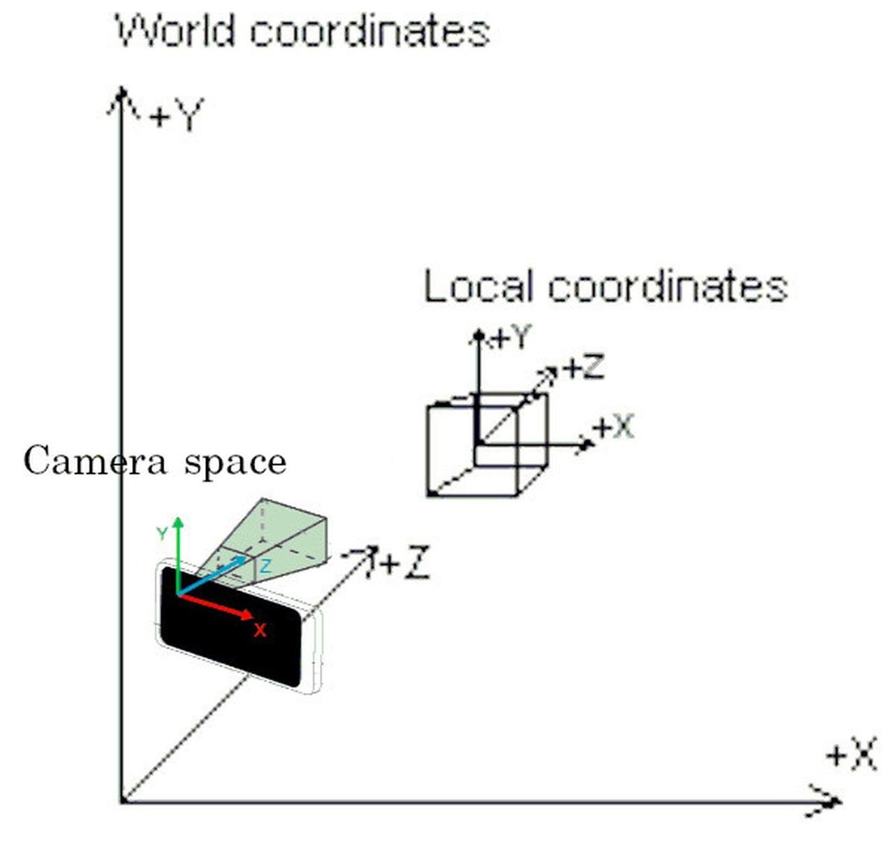
(Why different coordinate systems? For instance, the 3D engine uses a local coordinate relative to the model object and a world coordinate to store the shape data; there's a matrix that transforms world coordinates into the camera's coordinate system; and there can be a matrix that transforms the camera space coordinates into perspective projection as displayed on screen.)
Then, the 3D engine sends these data to shaders to calculate how each pixel on the screen is rendered. Shaders work in two main stages: vertex shaders and fragment shaders.
Vertex Shader: This shader assigns a final position on screen for each vertex of the 3D model. This is done by applying transformation and projection matrices to the 3D model's vertex coordinates. At this stage, it is also possible to add special effects to the vertices, such as adding ripples to the model surface, by applying additional transformation to its vertex coordinates. The vertex Shader also performs calculations relevant to lightings such as normal vectors and pass these variables to the fragment shader (see below).
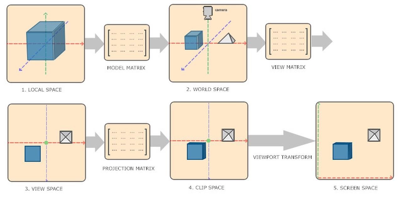
Vertex shader calculates the clip space coordinates for model vertices. Pixel position on screen can be extracted from the components of clip space coordinates. (Image Source: Learn OpenGL)
Fragment Shader: Also known as the pixel shader, it operates on every pixel within the primitive generated by the vertex shader. The fragment shader receives variables such as the normal vector calculated from the vertex shader, and calculates the pixel's final color. It handles visual effects such as lighting, materials, and textures.
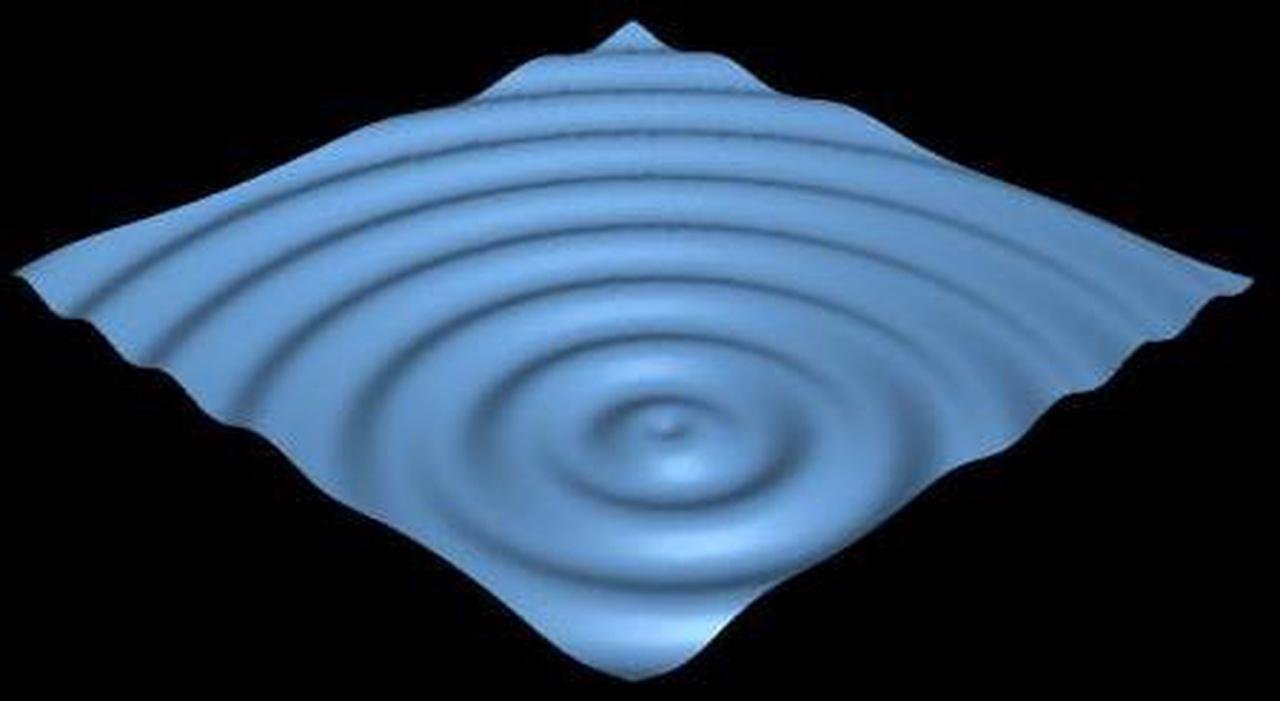
Adding ripples to model surfaces can be achieved by applying transformations to vertex coordinates from the vertex shader. Fragment shader then handles lighting and shadows, and assigns color to the pixel.
Example 1 - Show the Object
In the first example, we create two spheres in Three.js - on the right side, we use MeshBasicMaterial from Three.js, which has its default render style; on the left side, we will write a simple shader to display the object by setting all pixels of the model to white, which mimics the effect of MeshBasicMaterial. You can change viewing angle by dragging your mouse on the canvas.
As seen above, both our shader (left) and Three.js MeshBasicMaterial (right) renders the entire sphere as pure white. Here's our shader code:
For each vertex, the following vertex shader program get executed:
// vertex shader
void main() {
  gl_Position = projectionMatrix * modelViewMatrix * vec4(position, 1.0);
}
Let's break it down. gl_Position, projectionMatrix, modelViewMatrix, and position are special variables in GLSL, so you don't need to explicitly declare it.
The task for this shader is to assign a value to gl_Position, representing the final position for the vertex displayed on screen.
position is a 3D vector representing the vertex coordinate in the model's local coordinate system. This vector is appended to 1.0 to form a 4D vector, this is because computer graphics often uses 4x4 matrices in order to combine all type of transformations, including scaling, translation, and perspective projection, some of which cannot be encoded by 3x3 matrices. For details, see these examples: translation / translation, scaling, rotation / perspective projection.
modelViewMatrix transforms the vertex from its local model space to camera space. It can also be written as viewMatrix * modelMatrix.
Finally, the projectionMatrix handles perspective projection. It transforms the vertex from the 3D world space to device coordinates. This vector is assigned to gl_Position. This vector is also a 4D vector, but from this vector, the 2D coordinate in screen space can be directly extracted from its components without additional matrix computation (link).
For each pixels, the following fragment shader program get executed:
// fragment shader
void main() {
  gl_FragColor = vec4(1.0);
}
The goal of the fragment shader is to assign a 4D vector to gl_FragColor, representing the (red, green, blue, alpha) value for that pixel, where alpha is the opacity. Our example code assigns every pixel to an opaque white.
Full code:
let mesh1, mesh2, renderer, scene, camera, controls;

function init() {
  // renderer
  renderer = new THREE.WebGLRenderer();
  renderer.setSize(window.innerWidth, window.innerHeight);
  document.body.appendChild(renderer.domElement);

  // scene
  scene = new THREE.Scene();

  // camera
  camera = new THREE.PerspectiveCamera(40, window.innerWidth / window.innerHeight, 1, 10000);
  camera.position.set(0, 0, 300);

  // controls
  controls = new OrbitControls(camera, renderer.domElement);

  // geometry
  const geometry = new THREE.SphereGeometry(25);

  // material
  const shaderMaterial = new THREE.ShaderMaterial({
    vertexShader: `
      void main() {
        gl_Position = projectionMatrix * modelViewMatrix * vec4(position, 1.0);
      }
    `,
    fragmentShader: `
      void main() {
        gl_FragColor = vec4(1.0);
      }
    `,
  });

  const basicMaterial = new THREE.MeshBasicMaterial({color: 0xffffff});

  // mesh
  mesh1 = new THREE.Mesh(geometry, shaderMaterial);
  mesh2 = new THREE.Mesh(geometry, basicMaterial);
  mesh1.position.x = -50;
  mesh2.position.x = 50;
  scene.add(mesh1);
  scene.add(mesh2);
}

function animate() {
  requestAnimationFrame(animate);
  renderer.render(scene, camera);
}
Example 2 - Realistic Lighting
In the next example, we give more realistic lightings to the spheres by considering the direction of the light. On the right side, we use MeshPhongMaterial from Three.js; on the left side, we mimic MeshPhongMaterial with custom shader.
In this example, the spheres appear more realistic. This is achieved by considering a "light source", and we assign brighter colors to regions facing the light, and darker colors to regions that has a larger angle to the light source. Here's our shader code:
// vertex shader
varying vec3 vNormal;
void main() {
  vNormal = normal;
  gl_Position = projectionMatrix * modelViewMatrix * vec4(position, 1.0);
}
In the above vertex shader, normal is a special variable provided by GLSL. normal is accessible from the vertex shader, but not from the fragment shader. We declare a "varying" variable vNormal to store it and pass it down to the fragment shader. Since the vertex shader is executed for each vertex, this variable is holding the normal vector on that vertex point.
// fragment shader
varying vec3 vNormal;
void main() {
  vec3 light = vec3(0.0, 0.0, 1.0);
  light = normalize(light);
  float dProd = max(0.0, dot(vNormal, light));
  vec3 color = pow(dProd, 0.5) * vec3(1.0); // 0.5 because of gamma correction
  gl_FragColor = vec4(color, 1.0);
}
In the fragment code, we declare the varying variable vNormal again, and this variable will automatically be assigned to a value calculated from the vertex shader.
varying : Since the vNormal in the vertex shader is calculated for a vertex, while the fragment shader expect the normal vector corresponding to a pixel inside a triangle (defined by 3 vertices), the vNormal variable in the fragment shader is assigned to a value interpolated from the 3 vNormal values calculated from vertex shaders. When a variable in a vertex shader is declared using the varying keyword, the value will be automatically interpolated from neighboring vertices when the fragment shader receives the variable.
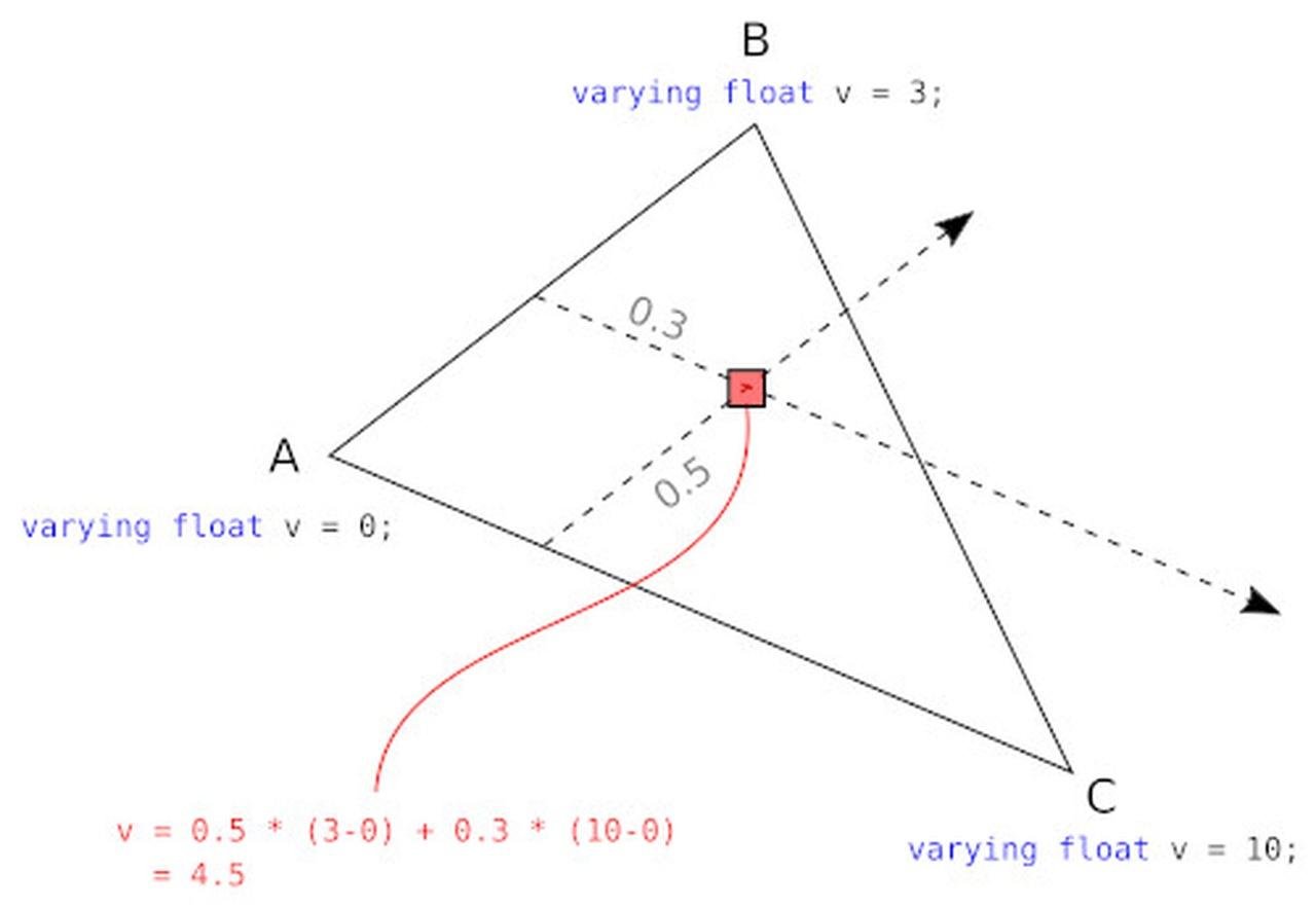
varying: interpolating from vertex. (Image Source: neeh @ stackoverflow)
In the above code we define a light source and computes its dot prodoct with the normal vectors at each pixel. In principle we could assign brightness to this value with gl_FragColor = vec4(dProd, dProd, dProd, 1.0), so surfaces facing towards the light source will be bright, and sufaces perpendicular to the light will be dark. However, we usually apply a gamma correction to the brightness value. This is because our visual perception sensitivity to brightness levels, the light energy density (luminosity) and computer color encodings are not linearly correlated to each other (see link). Here the square root is applied to approximate the gamma correction.

Comparison: with and without gamma correction.
Full code:
let mesh1, mesh2, renderer, scene, camera, light, controls;

function init() {
  // renderer
  renderer = new THREE.WebGLRenderer();
  renderer.setSize(window.innerWidth, window.innerHeight);
  document.body.appendChild(renderer.domElement);

  // scene
  scene = new THREE.Scene();

  // camera
  camera = new THREE.PerspectiveCamera(40, window.innerWidth /
window.innerHeight, 1, 10000);
  camera.position.set(0, 0, 300);

  // light
  light = new THREE.DirectionalLight(0xffffff, 3.05);
  light.position.set(0, 0, 1);
  scene.add(light);

// controls
  controls = new OrbitControls(camera, renderer.domElement);

// geometry
  const geometry = new THREE.SphereGeometry(25);

// material
  const shaderMaterial = new THREE.ShaderMaterial({
    vertexShader: `
      varying vec3 vNormal;
      void main() {
        vNormal = normal;
        gl_Position = projectionMatrix * modelViewMatrix * vec4(position, 1.0);
      }
    `,
    fragmentShader: `
      varying vec3 vNormal;
      void main() {
        vec3 light = vec3(0.0, 0.0, 1.0);
        light = normalize(light);
        float dProd = max(0.0, dot(vNormal, light));
        vec3 color = pow(dProd, 0.5) * vec3(1.0); // 0.5 because of gamma correction
        gl_FragColor = vec4(color, 1.0);
      }
    `,
  });

  const phongMaterial = new THREE.MeshPhongMaterial({color: 0xffffff});

  // mesh
  mesh1 = new THREE.Mesh(geometry, shaderMaterial);
  mesh2 = new THREE.Mesh(geometry, phongMaterial);
  mesh1.position.x = - 50;
  mesh2.position.x = 50;
  scene.add(mesh1);
  scene.add(mesh2);
}

function animate() {
  requestAnimationFrame(animate);
  renderer.render(scene, camera);
}
Example 3 - Gaussian Distribution
In this example, we write a shader to render an effect not built-in in Three.js. We will render a 3D Gaussian distribution.
We acheive this effect by adjusting the pixel's transparency based on the surface angle to the incoming light, and we plot it on the left. Because the boundary is transparent, it creates an illusion that makes it hard to see what happened. Therefore, for comparison, we create a second shader very slightly different than the first one - instead of adjusting the transparency, it adjust its brightness - and we plot it on the right. The second sphere will be entirely opaque and you can see the boundary of the sphere.
// shader 1 (left)

// vertex shader
varying vec3 vNormal;
varying vec3 vViewPosition;
void main() {
  vec4 mvPosition = modelViewMatrix * vec4(position, 1.0);
  vViewPosition = -mvPosition.xyz;
  vNormal = normalize(normalMatrix * normal);
  gl_Position = projectionMatrix * mvPosition;
}

// fragment shader
varying vec3 vNormal;
varying vec3 vViewPosition;
void main() {
  vec3 normal = normalize(vNormal);
  vec3 lightDir = normalize(vViewPosition);
  float dotProduct = max(dot(normal, lightDir), 0.0);
  float alpha = pow(dotProduct,4.0)*0.5;
  gl_FragColor = vec4(vec3(1.0), alpha);
}
For the vertex shader, the (negative) vertex position in world space is passed to vViewPosition, which will be used as the (fake) light source direction. The direction of the "light" connects the camera to the rendered target. normalMatrix is a special variable that represents the tranformation matrix for normal vectors from object space to camera space. The reason for applying the transformation is that now the "light" direction is always relative to the camera, so we also want the normal vector in camera space.
In the fragment shader, we apply the dot product between the "light" and the normal vector. We tranform this value into an approximated gaussian by raising it to the 4th power. This is a trick due to the fact that for any function which can be approximated by (x^2 - 1) at the center, raising it to a large exponent will approximate a gaussian. We use this value to set the transparency.
// shader 2 (right)

// vertex shader
... // same as in shader 1

// fragment shader
varying vec3 vNormal;
varying vec3 vViewPosition;
void main() {
  ... // same as in shader 1
  gl_FragColor = vec4(vec3(1.0)*alpha, 1.0);
}
Shader 2 simply uses the "alpha" value to assign the brightness, and the actual alpha channel is assigned to 1.0 (opaque) for all points. Try dragging your mouse on the above canvas to observe both sphere from different view angles.
Full Code:
let mesh1, mesh2, renderer, scene, camera, light, controls;

function init() {
  // renderer
  renderer = new THREE.WebGLRenderer();
  renderer.setSize(window.innerWidth, window.innerHeight);
  document.body.appendChild(renderer.domElement);

  // scene
  scene = new THREE.Scene();
  scene.background = new THREE.Color(0x000010);

  // camera
  camera = new THREE.PerspectiveCamera(40, window.innerWidth / window.innerHeight, 1, 10000);
  camera.position.set(0, 0, 300);

  // controls
  controls = new OrbitControls(camera, renderer.domElement);

  // geometry
  const geometry = new THREE.SphereGeometry(25);

  // material
  const shaderMaterial1 = new THREE.ShaderMaterial({
    transparent: true,
    vertexShader: `
      varying vec3 vNormal;
      varying vec3 vViewPosition;
      void main() {
        vec4 mvPosition = modelViewMatrix * vec4(position, 1.0);
        vNormal = normalize(normalMatrix * normal);
        vViewPosition = -mvPosition.xyz;
        gl_Position = projectionMatrix * mvPosition;
      }
    `,
    fragmentShader: `
      varying vec3 vNormal;
      varying vec3 vViewPosition;
      void main() {
        vec3 normal = normalize(vNormal);
        vec3 lightDir = normalize(vViewPosition);
        float dotProduct = max(dot(normal, lightDir), 0.0);
        float alpha = pow(dotProduct,4.0);
        gl_FragColor = vec4(vec3(1.0), alpha*0.5);
      }
    `,
  });

  const shaderMaterial2 = new THREE.ShaderMaterial({
    transparent: true,
    vertexShader: `
      varying vec3 vNormal;
      varying vec3 vViewPosition;
      void main() {
        vec4 mvPosition = modelViewMatrix * vec4(position, 1.0);
        vNormal = normalize(normalMatrix * normal);
        vViewPosition = -mvPosition.xyz;
        gl_Position = projectionMatrix * mvPosition;
      }
    `,
    fragmentShader: `
      varying vec3 vNormal;
      varying vec3 vViewPosition;
      void main() {
        vec3 normal = normalize(vNormal);
        vec3 lightDir = normalize(vViewPosition);
        float dotProduct = max(dot(normal, lightDir), 0.0);
        float alpha = pow(dotProduct,4.0);
        gl_FragColor = vec4(vec3(1.0)*alpha*0.5, 1.0);
      }
    `,
  });

  // mesh
  mesh1 = new THREE.Mesh(geometry, shaderMaterial1);
  mesh2 = new THREE.Mesh(geometry, shaderMaterial2);
  mesh1.position.x = - 50;
  mesh2.position.x =   50;
  scene.add(mesh1);
  scene.add(mesh2);
}

function animate() {
  requestAnimationFrame(animate);
  renderer.render(scene, camera);
}
Final Demo
In this example, we add animations and changes the colors.
The color is specified from Three.js in the "uniforms" object,
...
    uniforms: {
      color: { value: new THREE.Color(0xffffff) },
  	},
...
"uniforms" is a javascript object that can be modified, and it will be passed to the "uniform" variable in both the vertex and the fragment shaders, thus changing the color at runtime.
uniform vec3 color;
Full code:
let mesh1, mesh2, mesh3, renderer, scene, camera, light, controls;

function init() {
  // renderer
  renderer = new THREE.WebGLRenderer();
  renderer.setSize(window.innerWidth, window.innerHeight);
  document.body.appendChild(renderer.domElement);

  // scene
  scene = new THREE.Scene();

  // camera
  camera = new THREE.PerspectiveCamera(40, window.innerWidth / window.innerHeight, 1, 10000);
  camera.position.set(0, 0, 300);

  // controls
  controls = new OrbitControls(camera, renderer.domElement);

  // geometry
  const geometry = new THREE.SphereGeometry(50,40,20);

  // material
  const shaderMaterial = new THREE.ShaderMaterial({
    uniforms: {
      color: { value: new THREE.Color(0xffffff) },
  	},
    transparent: true,
    blending: THREE.AdditiveBlending,
    depthTest: false,
    depthWrite: false,
    vertexShader: `
      varying vec3 vNormal;
      varying vec3 vViewPosition;
      void main() {
        vec4 mvPosition = modelViewMatrix * vec4(position, 1.0);
        vNormal = normalize(normalMatrix * normal);
        vViewPosition = -mvPosition.xyz;
        gl_Position = projectionMatrix * mvPosition;
      }
    `,
    fragmentShader: `
      #define M_PI 3.1415926535897932384626433832795
      uniform vec3 color;
      varying vec3 vNormal;
      varying vec3 vViewPosition;
      void main() {
        vec3 normal = normalize(vNormal);
        vec3 lightDir = normalize(vViewPosition);
        float dp = max(dot(normal, lightDir), 0.0);
        float alpha = pow(dp,6.0);
        gl_FragColor = vec4(color.xyz, alpha*0.5);
      }
    `,
  });

  // mesh
  mesh1 = new THREE.Mesh(geometry, shaderMaterial.clone());
  mesh2 = new THREE.Mesh(geometry, shaderMaterial.clone());
  mesh3 = new THREE.Mesh(geometry, shaderMaterial.clone());
  mesh1.position.z = - 50;
  mesh2.position.z =   0;
  mesh3.position.z =   0;
  scene.add(mesh1);
  scene.add(mesh2);
  scene.add(mesh3);
}

function animate() {
  requestAnimationFrame(animate);
  const time = Date.now() * 0.001;
  mesh1.position.x = Math.sin(time * 0.65) * 50;
  mesh1.position.y = Math.sin(time * 0.7 + Math.PI/2) * 40;
  mesh1.position.y = Math.sin(time * 0.3) * 60;
  mesh2.position.x = - mesh1.position.x * 0.3;
  mesh3.position.x = Math.sin(time * 0.7) * 70;
  mesh3.position.y = Math.sin(time * 0.3 + Math.PI/2) * 30;
  mesh3.position.y = Math.sin(time * 0.5) * 40;
  mesh3.material.uniforms.color.value.setHSL( Math.sin(time * 0.2), 0.5, 0.5 );
  renderer.render(scene, camera);
}